著名医師による解説が無料で読めます
すると翻訳の精度が向上します
後頭部から軸から軸から軸から軸から軸への固定は、後部手術の病歴を持つ一部の患者にとっては後部アプローチよりも適しています。後頭部と軸の間の複雑な骨の解剖学は、神経学的および血管構造に損傷のリスクが高いため、前頭軸から軸へのねじ固定を導くための正確なネジ軌道を持つことが重要です。3次元(3D)再建のために、上部頸椎の30のコンピューター断層撮影(CT)スキャンが得られました。シリンダー(半径1.75 mm)を描画して、前後の軸から軸への軌跡をシミュレートしました。模倣ネジを4つの異なる角度に調整し、測定しました。これは、最大化前後幅の値と、後頭部の左右幅(C0)からC1およびC1からC2ジョイントです。次に、3Dモデルを印刷し、3D画像から計算された角度を参照して、3Dモデルにネジを導入するために角度ガイドデバイスを使用しました。ネジ角はα1(左:4.99±4.59°、右:4.28±5.45°)からα2(左:20.22±3.61°、右:19.63±4.94°)の範囲であることがわかりました。側面図では、ネジ角はβ1(左:13.13±4.93°、右:11.82±5.64°)からβ2(左:34.86±6.00°;右:35.01±5.77°)の範囲でした。左側と右側のデータの間に統計的に有意な差は見つかりませんでした。3D印刷モデルでは、すべての前頭軸から軸から軸へのネジが正常に導入され、皮質の外側に浸透していませんでした。平均α4は12.00±4.11(左)および12.25±4.05(右)であり、平均β4は23.44±4.21(左)および22.75±4.41(右)でした。3Dプリントモデルでは、左側と右側の3Dデジタル画像から計算された3Dプリントモデルとα3とβ3のα4とβ4の間に有意差は見られませんでした。Angle Guideデバイスを支援すると、3D印刷されたC0からC2モデルの前頭軸から軸から軸から軸から軸へのネジ固定に最適なネジ軌道を実現できました。
後頭部から軸から軸から軸から軸から軸への固定は、後部手術の病歴を持つ一部の患者にとっては後部アプローチよりも適しています。後頭部と軸の間の複雑な骨の解剖学は、神経学的および血管構造に損傷のリスクが高いため、前頭軸から軸へのねじ固定を導くための正確なネジ軌道を持つことが重要です。3次元(3D)再建のために、上部頸椎の30のコンピューター断層撮影(CT)スキャンが得られました。シリンダー(半径1.75 mm)を描画して、前後の軸から軸への軌跡をシミュレートしました。模倣ネジを4つの異なる角度に調整し、測定しました。これは、最大化前後幅の値と、後頭部の左右幅(C0)からC1およびC1からC2ジョイントです。次に、3Dモデルを印刷し、3D画像から計算された角度を参照して、3Dモデルにネジを導入するために角度ガイドデバイスを使用しました。ネジ角はα1(左:4.99±4.59°、右:4.28±5.45°)からα2(左:20.22±3.61°、右:19.63±4.94°)の範囲であることがわかりました。側面図では、ネジ角はβ1(左:13.13±4.93°、右:11.82±5.64°)からβ2(左:34.86±6.00°;右:35.01±5.77°)の範囲でした。左側と右側のデータの間に統計的に有意な差は見つかりませんでした。3D印刷モデルでは、すべての前頭軸から軸から軸へのネジが正常に導入され、皮質の外側に浸透していませんでした。平均α4は12.00±4.11(左)および12.25±4.05(右)であり、平均β4は23.44±4.21(左)および22.75±4.41(右)でした。3Dプリントモデルでは、左側と右側の3Dデジタル画像から計算された3Dプリントモデルとα3とβ3のα4とβ4の間に有意差は見られませんでした。Angle Guideデバイスを支援すると、3D印刷されたC0からC2モデルの前頭軸から軸から軸から軸から軸へのネジ固定に最適なネジ軌道を実現できました。
Anterior occiput-to-axis screw fixation is more suitable than a posterior approach for some patients with a history of posterior surgery. The complex osseous anatomy between the occiput and the axis causes a high risk of injury to neurological and vascular structures, and it is important to have an accurate screw trajectory to guide anterior occiput-to-axis screw fixation. Thirty computed tomography (CT) scans of upper cervical spines were obtained for three-dimensional (3D) reconstruction. Cylinders (1.75 mm radius) were drawn to simulate the trajectory of an anterior occiput-to-axis screw. The imitation screw was adjusted to 4 different angles and measured, as were the values of the maximized anteroposterior width and the left-right width of the occiput (C0) to the C1 and C1 to C2 joints. Then, the 3D models were printed, and an angle guide device was used to introduce the screws into the 3D models referring to the angles calculated from the 3D images. We found the screw angle ranged from α1 (left: 4.99±4.59°; right: 4.28±5.45°) to α2 (left: 20.22±3.61°; right: 19.63±4.94°); on the lateral view, the screw angle ranged from β1 (left: 13.13±4.93°; right: 11.82±5.64°) to β2 (left: 34.86±6.00°; right: 35.01±5.77°). No statistically significant difference was found between the data of the left and right sides. On the 3D printed models, all of the anterior occiput-to-axis screws were successfully introduced, and none of them penetrated outside of the cortex; the mean α4 was 12.00±4.11 (left) and 12.25±4.05 (right), and the mean β4 was 23.44±4.21 (left) and 22.75±4.41 (right). No significant difference was found between α4 and β4 on the 3D printed models and α3 and β3 calculated from the 3D digital images of the left and right sides. Aided with the angle guide device, we could achieve an optimal screw trajectory for anterior occiput-to-axis screw fixation on 3D printed C0 to C2 models.
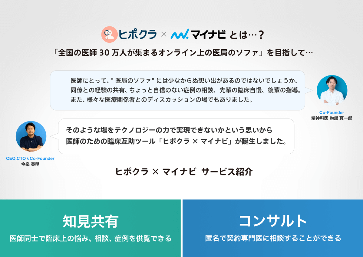
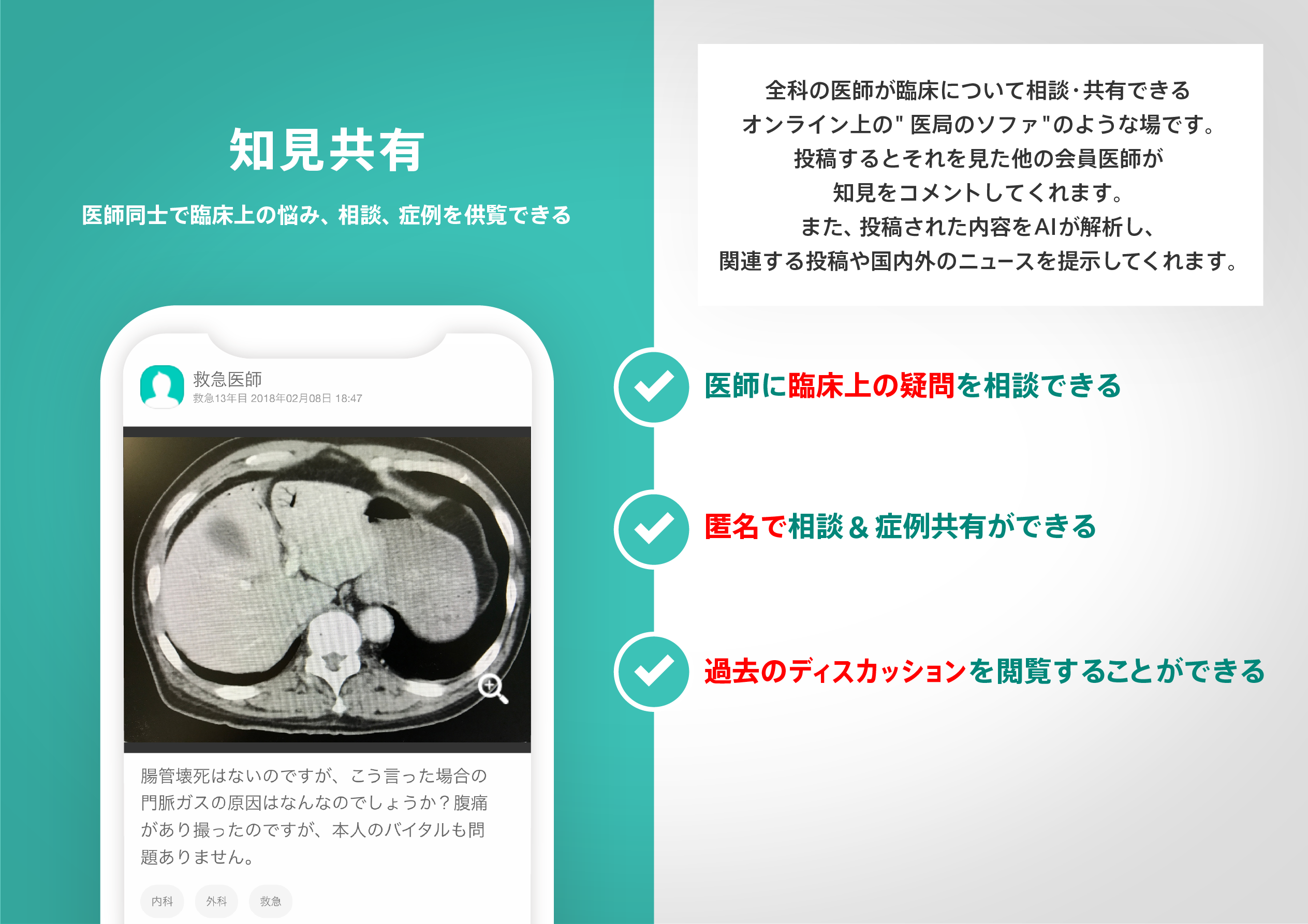
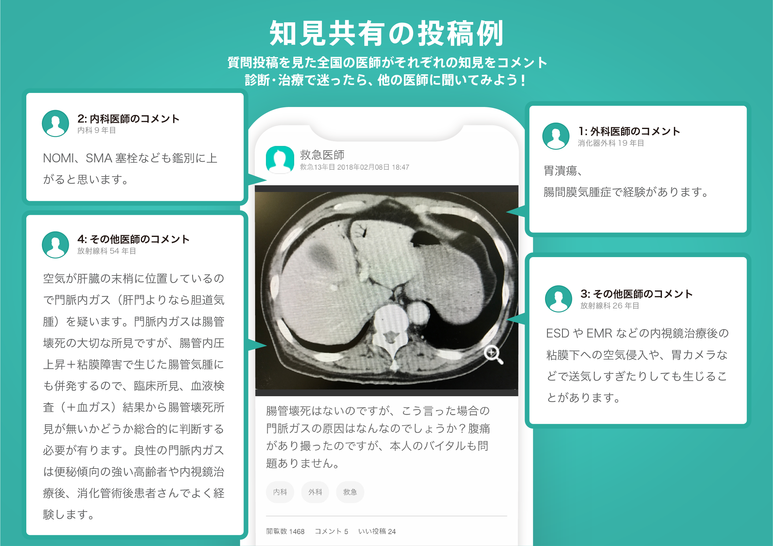
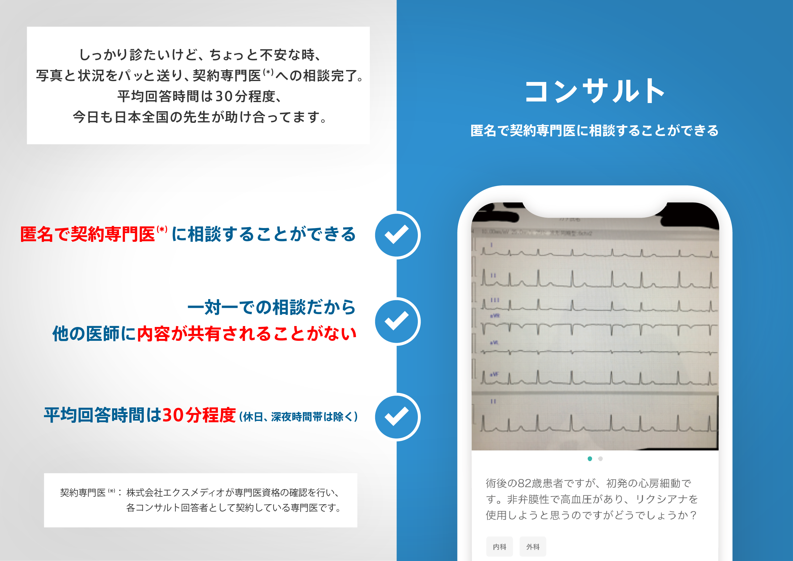
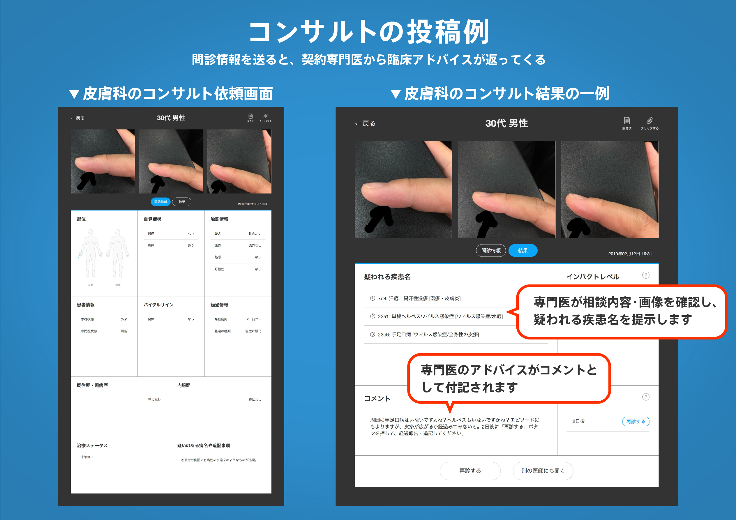
医師のための臨床サポートサービス
ヒポクラ x マイナビのご紹介

無料会員登録していただくと、さらに便利で効率的な検索が可能になります。